This video is an overview of the ZX1 loop modulation system. Here we will describe the major assemblies and their functions. Please note that, for illustration purposes, not all pneumatic hoses and electrical cables are shown.
The ZX1 retrofits onto several commercially available GC systems, including Agilent models 7890 A or B and 8890 gas chromatographs. A bench dewar assembly holds a charge of liquid nitrogen, which cools a stream of house supplied dry nitrogen gas to a temperature of about 77 Kelvin or -196 Celsius, cold enough to modulate C6 and larger organic molecules.
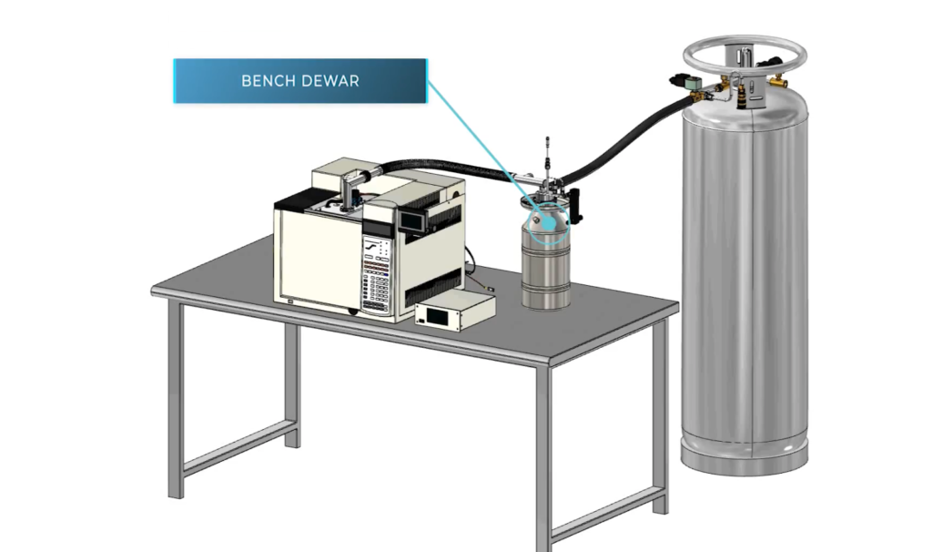
The user supplies the lab bench on which the GC is installed. Easy access to the back of the GC is required.
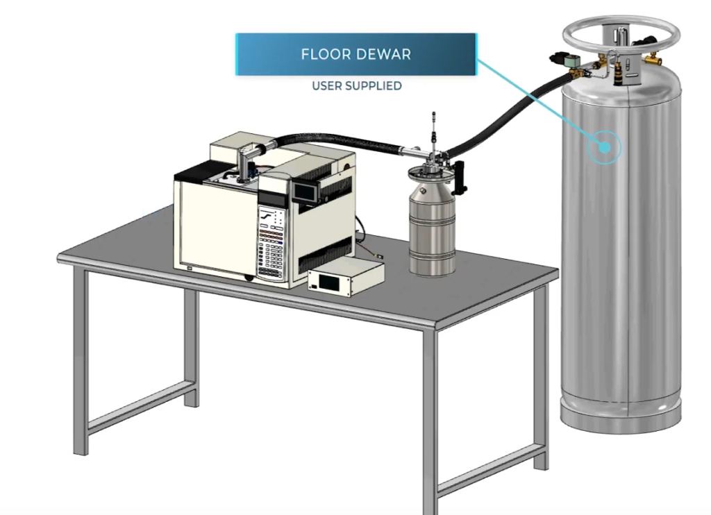
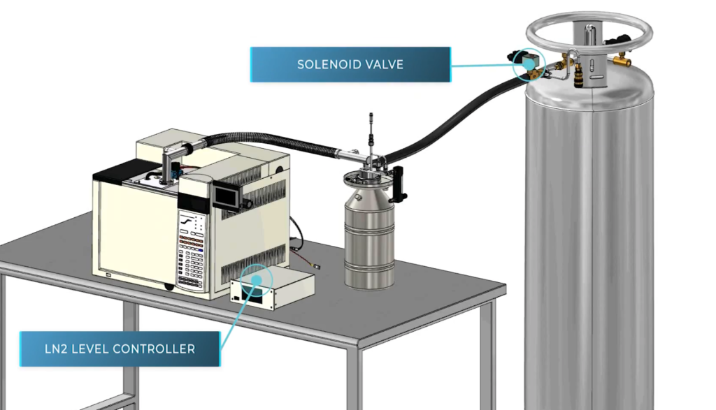
A floor dewar, also supplied by the user, feeds liquid nitrogen to the bench dewar via a solenoid valve.
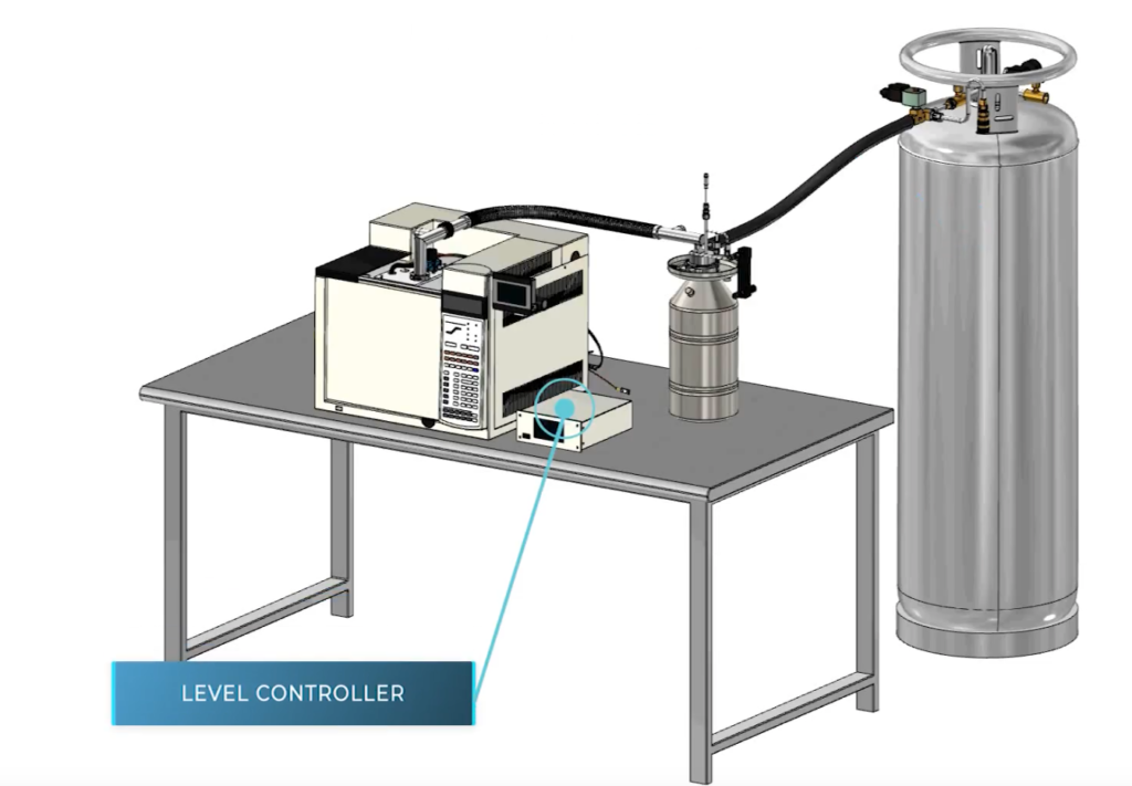
A liquid level controller senses and regulates the liquid nitrogen level in the bench dewar.
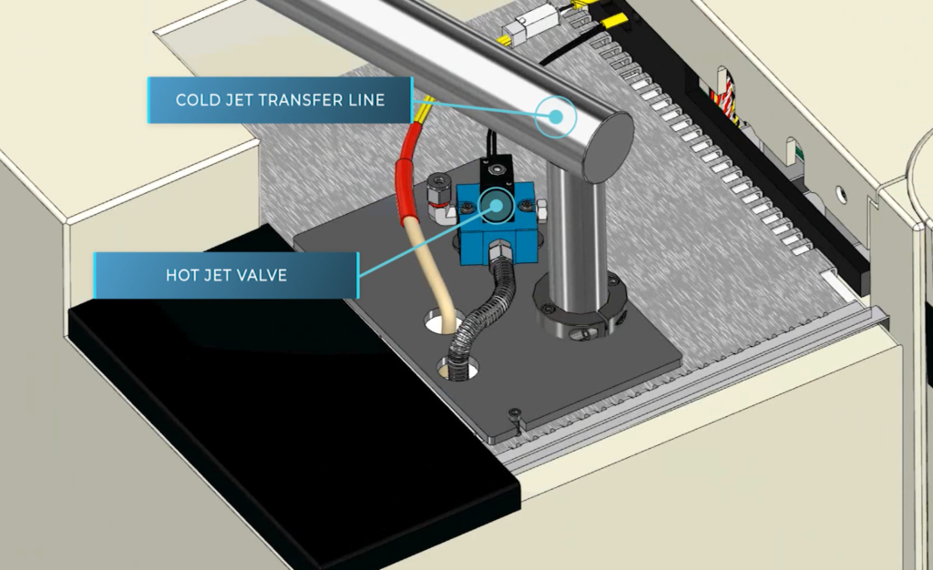
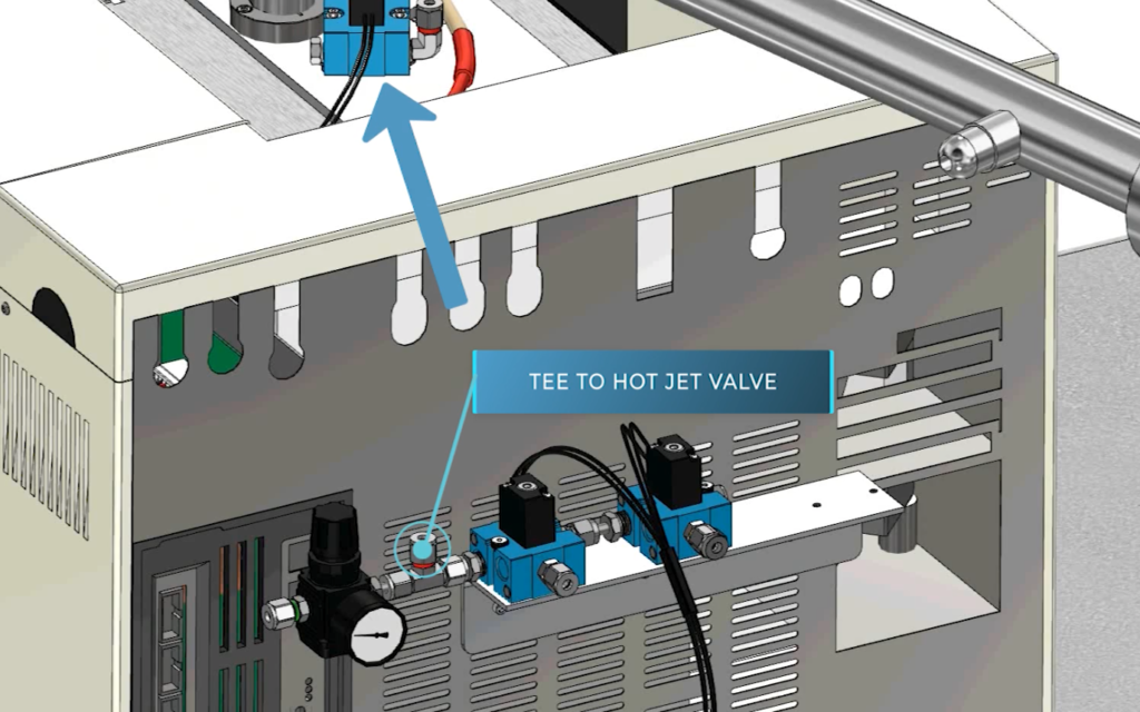
A hot jet valve mounted on top of the GC, supplies gas pulses to a hot jet assembly, located inside the GC oven. A cryogenic transfer line supplies refrigerated gas to a cold jet assembly, also located inside the GC oven.
A cold jet valve switches the cold gas supply on and off. Typically, the cold jet valve is turned off for the first minute of a run, turned on for the duration of a run, and left on between runs.
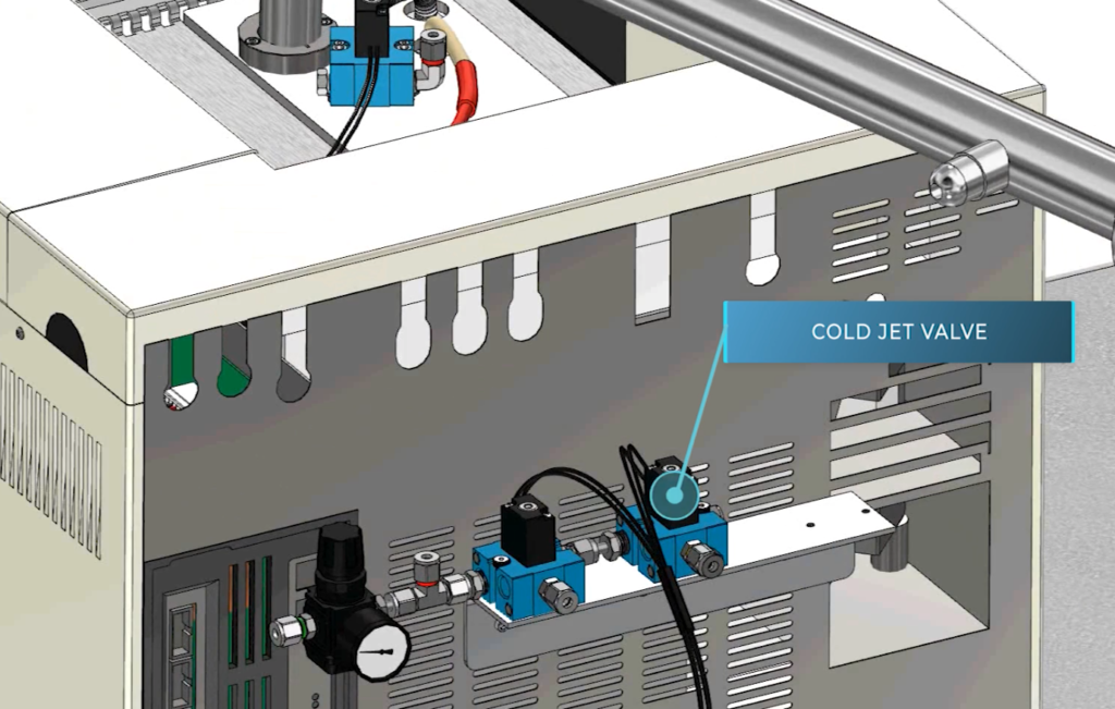
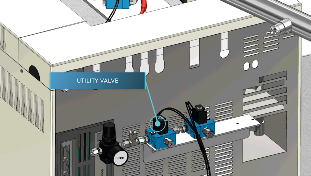
The kit includes a utility valve, which may be used to decrease the cold jet flow rate late in a run, a technique used for analysis of heavier organic species. (Contact Zoex for more details.)
A tee connector upstream of the utility valve feeds room temperature dry nitrogen gas to the hot jet valve, located on top of the GC.
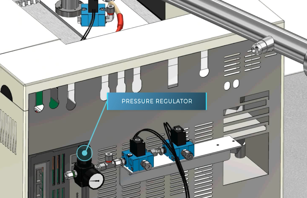
A pressure regulator supplies 40 psi of house nitrogen to the valve pack. The nitrogen inlet is a 1/4-inch Swagelok fitting, which receives house nitrogen at a feed pressure of 100 psi.
The bench dewar assembly is a liquid nitrogen filled cryogenic heat exchanger, which refrigerates a flow of house nitrogen.
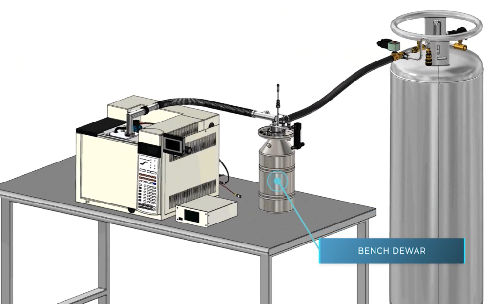
The flow rate, typically 10-15 liters per minute, is controlled by a manually operated gas flow controller.
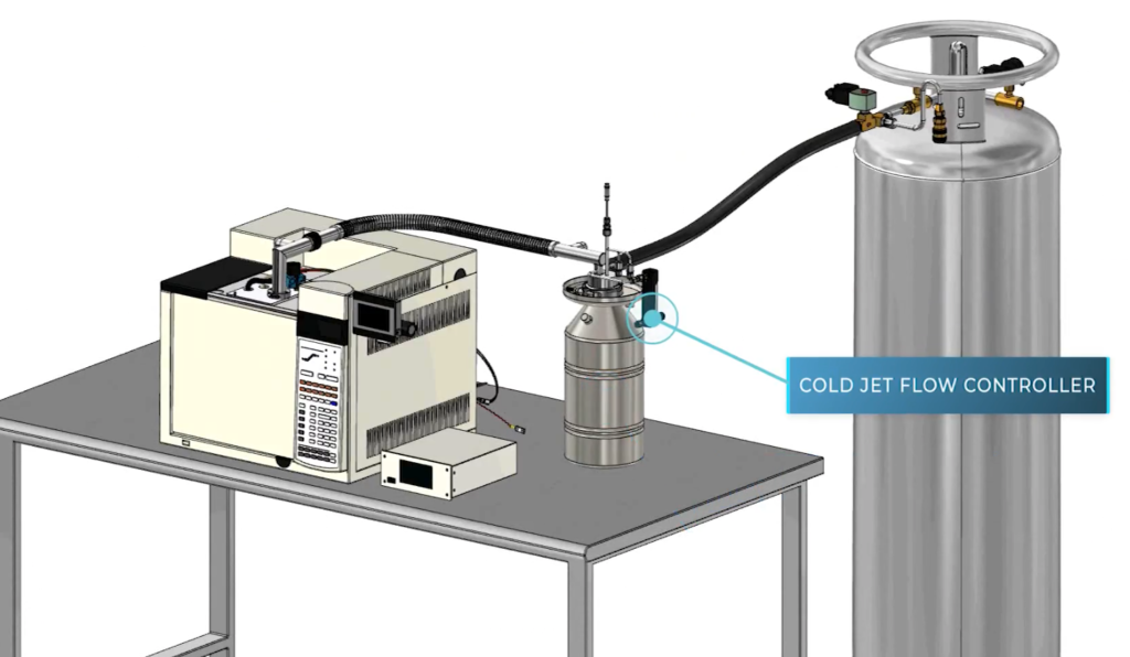
A liquid nitrogen level sensor inserts into the top of the bench dewar.
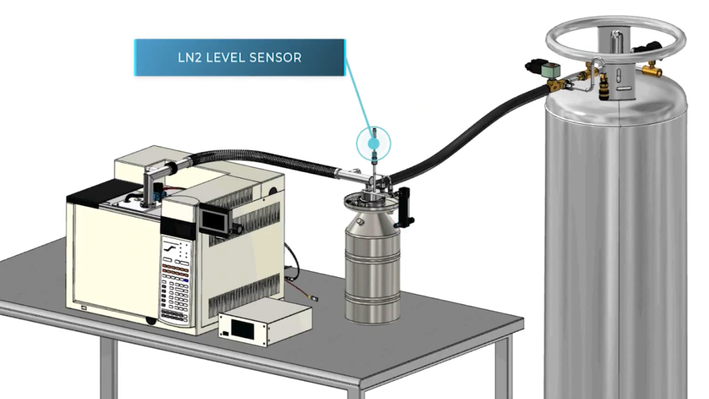
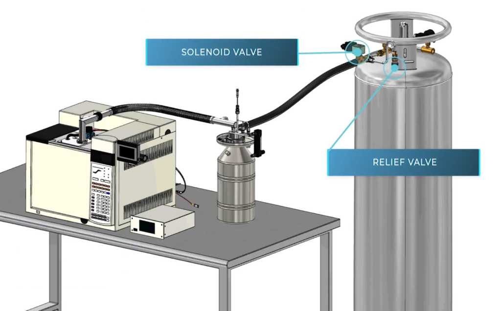
Dual relief valves on the bench dewar vent liquid nitrogen boil-off. A foam-insulated fill line conveys liquid nitrogen from the floor dewar to the bench dewar.
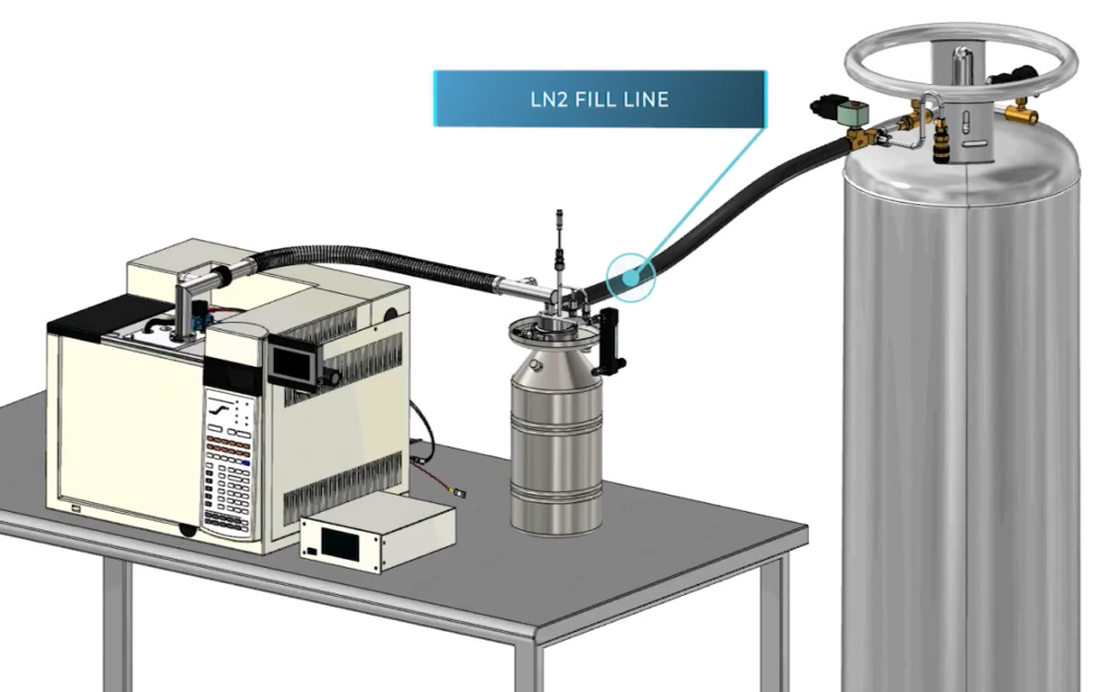
The floor dewar assembly, operated at an internal pressure of 24 psi, sits behind or to one side of the GC bench. A liquid nitrogen level controller communicates with the level sensor in the bench dewar and a solenoid valve on the floor dewar.
A relief valve prevents over-pressure upstream of the solenoid valve.
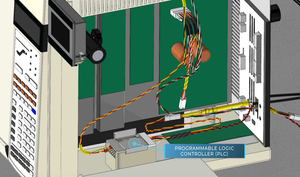
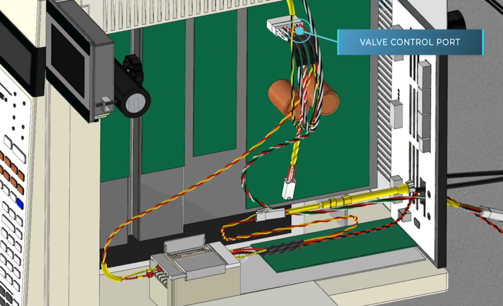
A programmable logic controller, or “PLC”, draws power from a DC power supply included in the kit. The PLC issues on-off signals to the hot jet valve, which effects the thermal modulation process. The hot jet valve draws power from a valve control port on the GC motherboard.
The hot jet valve draws power from a valve control port on the GC motherboard.
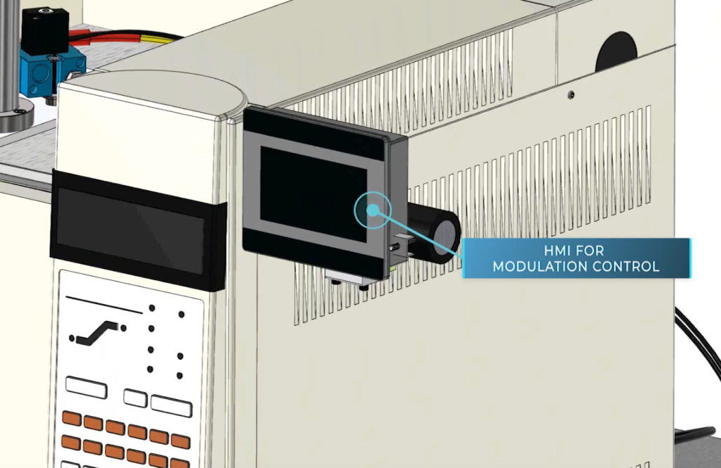
A touchscreen human-machine-interface, or HMI, controls the PLC. With the HMI touchscreen, the user sets the modulation period (i.e., the time between hot jet firings) and the duration of hot jet pulses, which remobilize trapped substances. A modulation period of 6 seconds and a pulse duration of 0.375 seconds are typical.
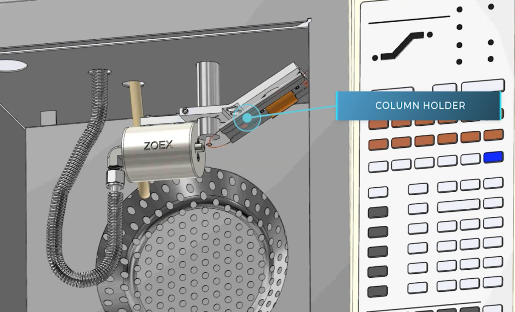
This is a view of the modulator assembly, mounted in the GC oven. Analytical columns are not shown.The modulator tube consists of a length of column, two portions of which pass through intersecting hot and cold gas jets. These two column portions form the so-called “loop”.
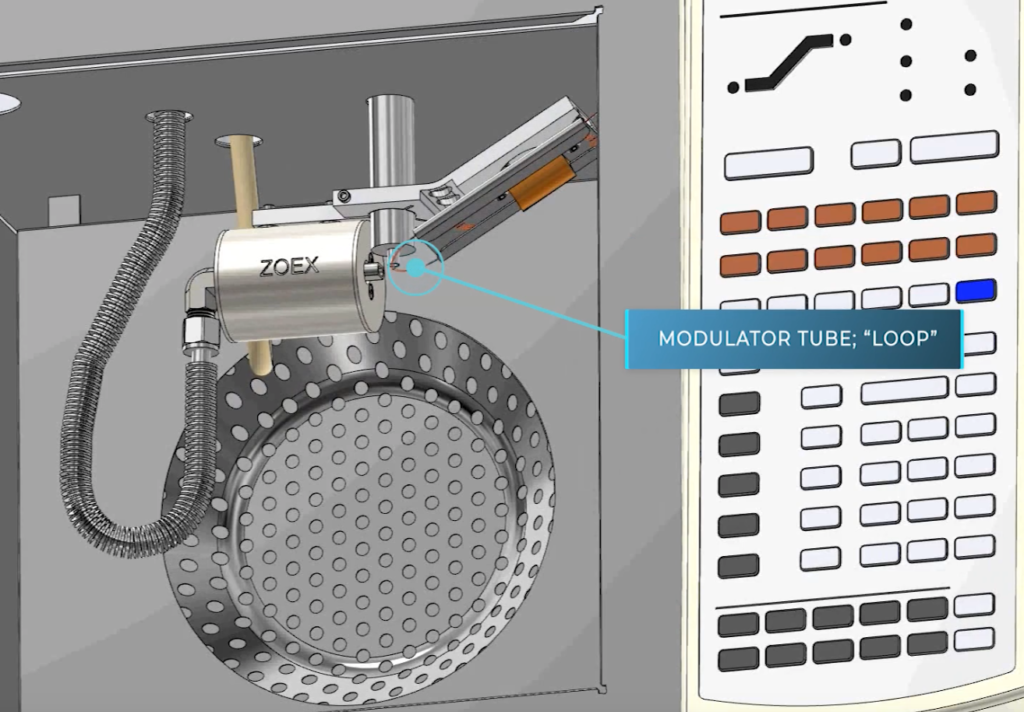
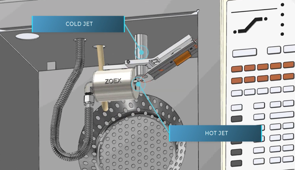
The cold jet, which is vacuum insulated, protrudes downward from the oven roof, passes through the head clamp, and then terminates about 2 mm above the loop “apex”, or extremum. There, the cold and hot jets periodically trap and remobilize analytes eluting from the primary column of the GCxGC column set.
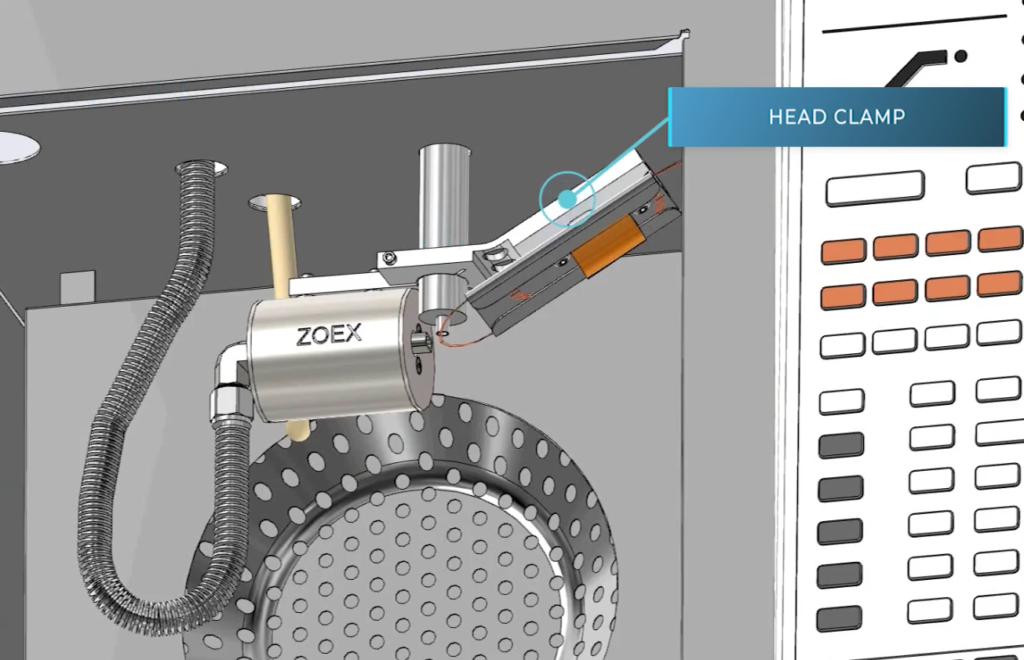

The modulator tube is wound into a “column holder”, which is part of the column set, and attaches to the head clamp.
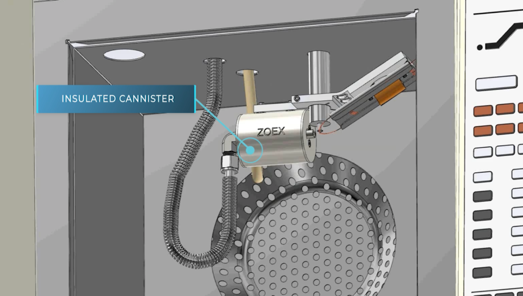
An insulated canister houses a hot jet body, a cartridge heater, and a platinum resistance temperature sensor.
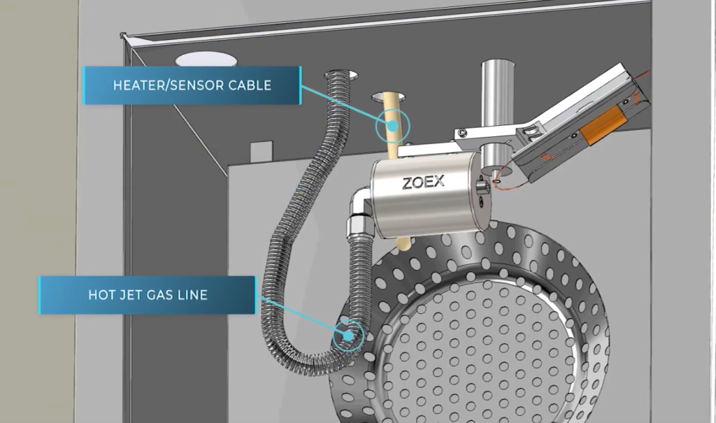
Hot jet temperature is controlled by a GC auxiliary thermal zone via a heater/sensor cable. A convoluted steel gas line feeds dry nitrogen gas to the hot jet, which pulses once at the start of each modulation cycle.
Repetitive cooling and heating of the loop extremum results in a GCxGC chromatogram.
To learn more, contact Zoex: info@zoex.com
