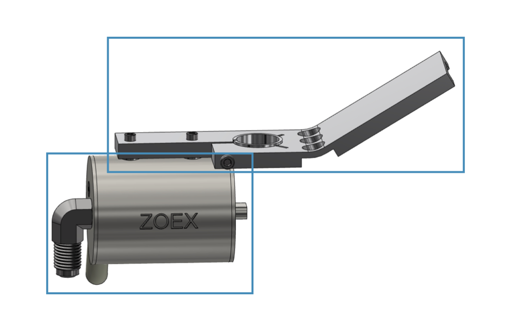
This assembly is the core of the Thermal Modulation System which consists of several sub-assemblies that we will now review.
The Head Clamp Assembly is included with the ZX1 and ZX2 Thermal Modulation Systems and is also available separately as a replacement module.
The Head Clamp Assembly consists of two subassemblies; the Head Clamp and the Hot Jet.
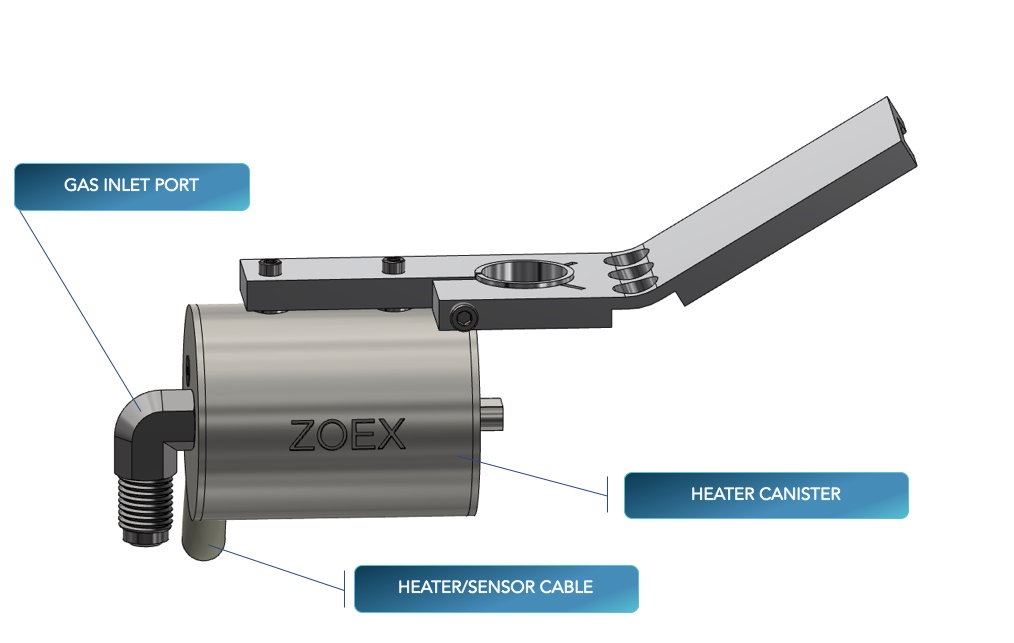
Key features of the Hot Jet Assembly are: a gas inlet port and a heater/sensor cable (shown here in partial view), which connects to a cartridge heater and a temperature sensor, housed within a heater canister.
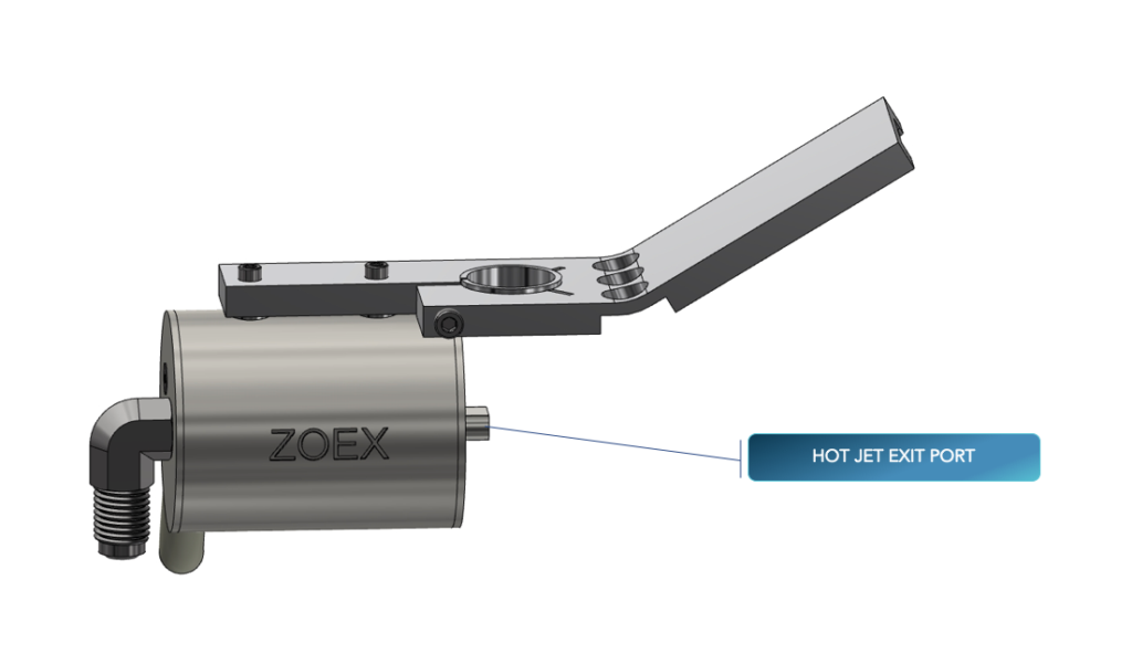
A heated jet of gas exits the hot jet exit port on the right.
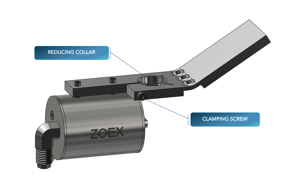
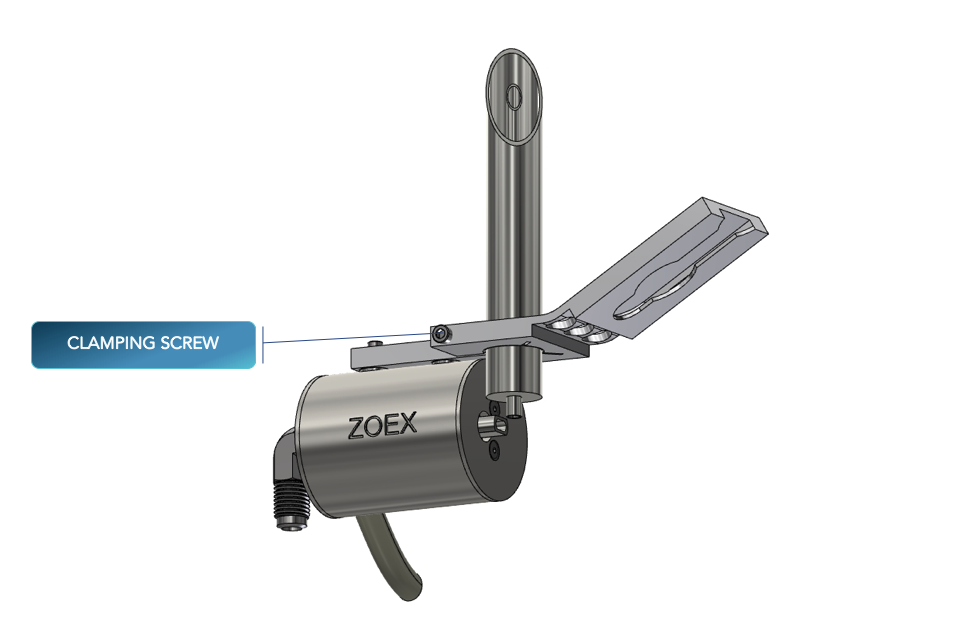
The head clamp assembly consists of the head clamp proper and two other parts: the clamping screw and the reducing collar. These last two parts secure the head clamp assembly to a cold jet transfer line as follows:
The cold jet assembly engages with the head clamp assembly. Turning the clamping screw clock-wise clamps the two assemblies together.
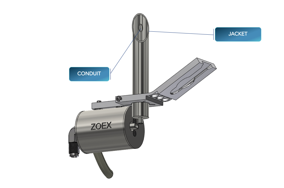
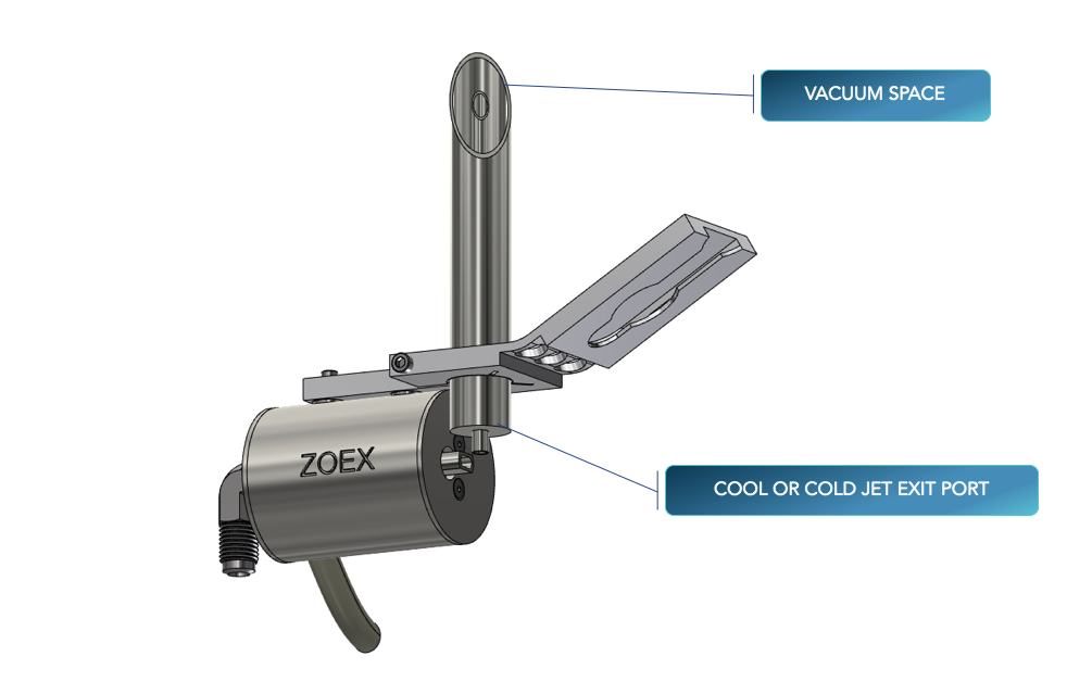
The cold jet assembly consists of an outer jacket and an inner conduit through which cool or cold gas flows.
The jacket and conduit are separated (and thermally insulated) by a permanent vacuum space. Cool or cold gas exits through the cold jet exit port.
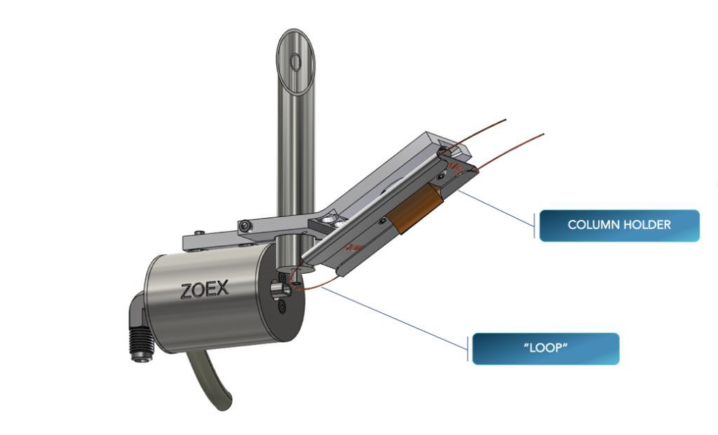
The column holder, which carries the modulator tube, slides into the head clamp. The apex or “extremum” of the so-called loop comes to rest at the intersection of the hot and cold jets.
This view shows proper alignment between the modulator loop extremum and the center of the hot jet exit port.
This view shows proper alignment between the modulator loop extremum and the center of the cold jet exit port.